Clamp Meter Accuracy at Low Current: A Distributor’s Guide to Zeroing and Batch QC
Learn how to assess clamp meter accuracy, low-current resolution, zero drift, jaw position, safety documents and batch consistency before ordering.
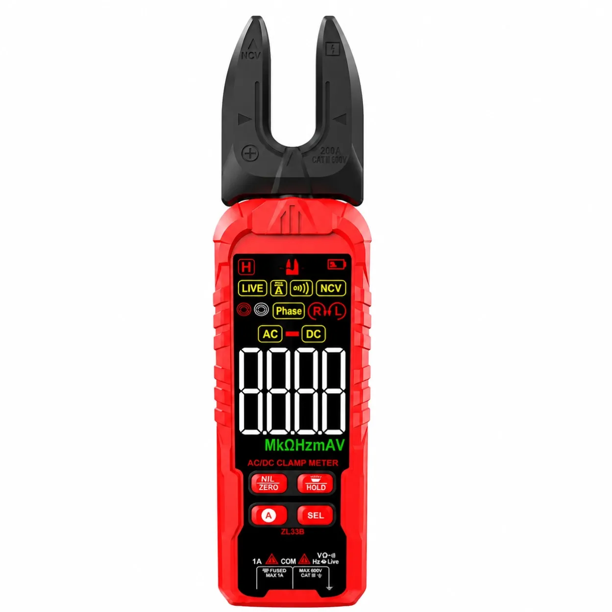
Clamp meter accuracy is easy to misunderstand when a specification sheet shows one impressive maximum-current value. For distributors, electrical wholesalers, automotive-tool buyers and private-label brands, the harder question is whether the meter produces stable, repeatable readings at the currents customers actually measure.
A compact 200 A clamp may be a good fit for control panels, HVAC equipment, motorcycles, cars and light industrial circuits. Yet its commercial value depends on more than the number printed on the housing. Resolution, the complete accuracy statement, DC zeroing, jaw closure, conductor position, external magnetic fields and batch consistency can all change the result.
This guide explains how to evaluate those factors before approving a sample or placing a production order.
What does clamp meter accuracy really mean?
Accuracy describes how close a displayed value is expected to be to the value established by a suitable reference under stated conditions. A clamp meter specification is commonly written in a form such as:
±(% of reading + digits)
The percentage term scales with the measured current. The digits term is tied to the least significant displayed digit on the selected range. That second term can be especially important near the bottom of a range.
Consider a purely illustrative specification of ±(2.0% of reading + 5 digits) on a range with 0.1 A resolution. At a 100.0 A reading, the percentage term is 2.0 A and the digit term contributes another 0.5 A. At a 2.0 A reading, the same five-digit term still contributes 0.5 A. The low-current result therefore carries a much larger relative uncertainty.
This is why buyers should never compare clamp meters using a percentage alone. Ask for the applicable range, resolution, digit term, frequency limits, operating conditions and any exclusions.
Accuracy, resolution, repeatability and stability are different
| Term | What it tells a buyer | What it does not prove |
|---|---|---|
| Accuracy | Expected closeness to a reference under specified conditions | That every function and range has the same performance |
| Resolution | The smallest displayed step on a selected range | That the last displayed digit is accurate or stable |
| Repeatability | How closely repeated results agree under the same setup | That the repeated value is close to the reference |
| Zero stability | How well the no-current baseline holds over time and after movement | Performance across the full current range |
| Batch consistency | How closely production units behave under one controlled test plan | Compliance with a standard unless the required tests and documents exist |
A high-resolution display can make a meter look precise while the reading still drifts. Conversely, a meter with modest display resolution can be entirely suitable for a technician who only needs to confirm whether a motor feeder is drawing 18 A or 28 A. The buying decision should start with the smallest current difference that would change a field decision.
Why low-current clamp measurements are demanding
A clamp meter senses the magnetic field produced by current in a conductor. As current becomes smaller, the useful field becomes less dominant relative to sensor offset, residual magnetism, nearby conductors, temperature effects and electrical noise.
For this reason, “200 A maximum” does not answer whether the same meter is suitable for a 50 mA standby-current diagnosis, a 0.8 A control load or a 12 A compressor. A buyer should establish both ends of the required measurement window.
Resolution must match the application
If a display changes in 0.1 A steps, it cannot show changes smaller than 0.1 A on that range. That may be acceptable for many mains-load checks but insufficient for low-current leakage work or automotive parasitic-drain diagnosis. A lower range with finer resolution can help, but only when its accuracy, noise and zero behavior are also controlled.
AC and DC performance may differ
Traditional current-transformer jaws respond to AC. DC-capable clamp meters use a sensor that can detect a steady magnetic field and normally require a zero or relative adjustment. A product page that says “AC/DC” may refer to voltage functions rather than both AC and DC current through the jaw. The current table and user manual must make the distinction explicit.
True RMS has a defined use
True RMS matters when measuring non-sinusoidal AC loads such as variable-speed drives, electronic power supplies and many modern HVAC controls. It does not automatically improve DC zero stability, low-current resolution or safety. Buyers should ask for the AC-current frequency range and any crest-factor limitations instead of treating “True RMS” as a general accuracy label.
Five setup factors that can move the reading
1. Zeroing the empty jaw
For DC current, close the empty jaw, keep all conductors outside it and use the zero or relative function according to the manual. The meter should be held in approximately the same orientation used for the measurement. Movement, nearby magnetic fields or temperature change can shift the baseline, so re-zeroing may be necessary.
2. Closing and cleaning the jaw
The jaw faces must close completely. Dirt, metal particles, damaged mating surfaces or mechanical play can alter the magnetic path. Incoming inspection should include a visual check, repeated opening and closing, and a comparison between gently released and firmly seated jaws.
3. Positioning one conductor correctly
Clamp around one current-carrying conductor, not a complete cable containing both outgoing and return conductors. Place the conductor at the alignment marks or optimum position specified by the manufacturer. Fluke instructions, for example, direct users to center the conductor, and published specifications for some clamp systems state that uncertainty assumes a centralized conductor at the optimum position.
4. Controlling nearby current paths
An adjacent high-current conductor can create an external magnetic field that affects the reading. This matters in crowded switchboards, motor-control cabinets and test fixtures. A useful sample test measures the same reference current with a second energized conductor placed at defined distances outside the jaw.
5. Allowing the reading to settle
Auto-ranging, filtering and True RMS conversion can require settling time. Define when the inspector records the value—such as after a stable display for several seconds—rather than letting each operator choose a different moment.
A distributor’s low-current sample-approval plan
A professional sample review does not require an elaborate laboratory, but it does require a controlled reference, a repeatable fixture and documented acceptance limits. The reference source and method should have uncertainty suitable for the decision being made.
- Define the application window. List the lowest, normal and highest currents customers will measure, separately for AC and DC.
- Review the complete specification. Record range, resolution, accuracy formula, frequency band, crest-factor limits, operating temperature and jaw opening.
- Verify function labeling. Confirm whether AC/DC applies to jaw current, probe voltage, or both.
- Inspect jaw mechanics. Check alignment, closure, spring force, mating surfaces and the ability to fit the intended conductors in real equipment.
- Check empty-jaw zero. Record the initial offset, the result after zeroing and drift over a defined interval.
- Test at several current points. Include at least one point near the lower useful limit, one mid-range point and one higher point.
- Repeat the measurement. Open and close the jaw between readings to include normal mechanical variation.
- Move the conductor. Compare the centered position with realistic off-center positions allowed by the manual.
- Rotate or reposition the meter. For DC tests, determine whether orientation requires re-zeroing.
- Check adjacent-field sensitivity. Introduce a controlled nearby conductor where the target market uses crowded panels.
- Compare multiple samples. Use several units from the pre-production sample, not one hand-selected instrument.
- Freeze the approved configuration. Record firmware, sensor, jaw components, PCB revision, accessories, labeling and packaging references.
How to set a practical batch QC plan
Incoming inspection should distinguish cosmetic checks from measurement checks. A sensible plan uses the same fixture, conductor position, current points, stabilization time and pass/fail rule for every lot.
| QC item | Why it matters | Record to keep |
|---|---|---|
| Jaw closure and alignment | Mechanical variation can change the magnetic path | Visual result and defect count |
| Zero offset and drift | Low-current DC readings can be dominated by baseline error | Before-zero, after-zero and timed values |
| Low, mid and high test points | One point cannot represent the whole range | Reference value, displayed value and calculated error |
| Repeat opening/closing | Reveals intermittent closure or position sensitivity | Series of repeated readings |
| Controls and display | Confirms zero, hold, range and mode behavior | Functional checklist |
| Labels and documents | Prevents model or market mismatch | Approved artwork and revision numbers |
Do not create acceptance limits by copying a competitor’s headline accuracy. Limits should come from the approved model specification, intended application, test-method uncertainty and agreed sampling plan. NIST measurement guidance also emphasizes that a calibration result is meaningful only with its associated measurement uncertainty and defined method.
Safety documents belong in the sourcing file
IEC 61010-2-032 addresses particular safety requirements for hand-held current clamps and current sensors. A CAT marking on a housing is not a complete compliance file. Buyers should request model-matched reports or declarations, verify rated voltage and measurement category, and check that jaws, input terminals, test leads and manuals describe the same approved configuration.
For leakage-current clamps, IEC 61557-13 introduces separate performance considerations, including external magnetic-field influence. A general-purpose 200 A clamp should not be marketed as a leakage-current instrument unless its range, resolution, accuracy and applicable documentation support that claim.
For more context, see ZYD’s guide to CAT III vs CAT IV measurement categories.
Matching the jaw to the customer
Jaw size is a trade-off, not a simple “larger is better” specification. A large jaw fits thicker conductors but can be awkward inside compact panels, vehicles and HVAC equipment. A narrow U-shaped jaw can improve access and make it easier to isolate one conductor, provided the intended cable fits and the specified measurement position is practical.
ZYD’s ZL33A/ZL33B compact clamp meter listing is positioned around a 200 A current class, 600 V voltage class and a 15 mm U-shaped jaw. The ZL35 clamp meter is another compact option aimed at automotive and general service tasks. Exact AC/DC current functions, range resolution, accuracy limits, safety category and supplied accessories should be confirmed for the chosen model and market before ordering.
If the buyer first needs a broader explanation of non-invasive current measurement, read why a clamp meter is useful for current measurement.
RFQ questions that prevent costly misunderstandings
- Does the jaw measure AC current, DC current or both?
- What are the ranges, resolutions and full accuracy expressions for each current mode?
- What frequency range and crest-factor conditions apply to AC-current accuracy?
- What zeroing procedure and residual offset are specified for DC current?
- What conductor position is used for the published accuracy?
- What is the jaw opening, and what cable sizes fit in the intended installation?
- Which model-matched safety reports, declarations and test-lead documents are available?
- What production checks control jaw alignment, sensor performance and zero drift?
- Can the supplier provide a multi-unit pre-production sample for comparison?
- How are engineering changes communicated after sample approval?
Frequently asked questions
Are clamp meters accurate at very low current?
Some are designed for low-current work, while many general-purpose clamps are optimized for higher currents. Check the lowest range, resolution, complete accuracy expression, zero stability and stated application. For very small leakage currents, use a clamp specifically designed and documented for that purpose.
Why does a DC clamp meter show a value with no wire inside?
The sensor may have a small offset caused by residual magnetism, orientation, temperature or nearby magnetic fields. Close the empty jaw and follow the manufacturer’s zeroing procedure. Persistent or excessive offset is a useful sample-approval and batch-QC finding.
Does the conductor have to be in the center of the jaw?
Follow the alignment marks or position stated in the manual. Many clamp specifications assume an optimum conductor position, and moving the conductor can introduce additional error. Position sensitivity should be tested during sample approval.
Can a clamp meter measure a whole power cable?
For normal load-current measurement, clamp around one conductor. If both outgoing and return conductors are inside the jaw, their magnetic fields largely cancel. Specialist leakage measurements use that principle, but they require suitable resolution and a different measurement objective.
Is a higher maximum current always better?
No. Maximum current must cover the application, but a customer may benefit more from finer low-range resolution, a smaller jaw, better access, clearer safety documentation or more consistent zero behavior.
How many samples should a distributor test?
One sample can confirm basic suitability but cannot demonstrate production variation. Use several pre-production units and define an ongoing lot-sampling plan based on order size, supplier history, risk and the consequences of a measurement failure.
Source clamp meters around the real measurement task
The strongest clamp meter offer is not the one with the longest feature list. It is the one whose current modes, useful range, resolution, accuracy, jaw geometry, safety file and production controls match the end customer’s work.
Explore ZYD’s test and measurement product catalog, or contact Shenzhen Zhanyueda Technology to discuss samples, mixed-SKU orders, distributor supply and OEM/private-label requirements. For a meaningful comparison, include the target market, expected conductor size, AC/DC current range, minimum useful reading, safety environment and required documentation in the RFQ.