Sep 4, 2026Buying Guides
How to Diagnose Intermittent Electrical Faults: Multimeter vs Oscilloscope
Learn how to diagnose intermittent electrical faults with a multimeter and oscilloscope, including dropouts, triggering, logging and safe probing.
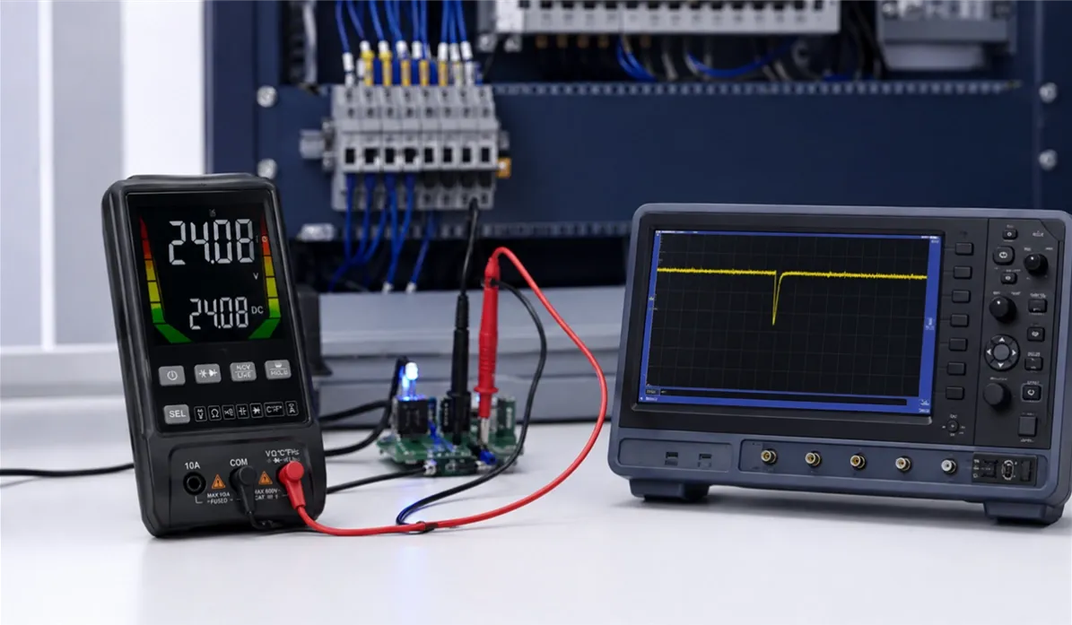
An intermittent fault is difficult for one simple reason: the circuit often looks healthy when the technician is measuring it. A machine resets once per shift, a sensor drops out only when a motor starts, or a controller fails after the enclosure warms up. By the time the test leads are connected, the evidence is gone.
The right question is not whether a multimeter or an oscilloscope is the “better” instrument. It is which tool can capture the fault on the time scale where it occurs. A digital multimeter is usually the fastest way to establish the electrical baseline. An oscilloscope becomes necessary when the failure involves a short dropout, noise, waveform distortion or the timing between two events.
This guide explains how technicians—and the distributors who supply them—can choose the right instrument and build a repeatable troubleshooting process.
Quick answer: multimeter or oscilloscope?
Start with a multimeter when you need an accurate value: steady AC or DC voltage, resistance, continuity, current, frequency or a voltage drop under load. Use Min/Max capture or logging when the suspected change lasts long enough for the meter to record.
Move to an oscilloscope when the average value looks normal but the equipment still misbehaves. A scope shows voltage against time, so it can reveal brief dropouts, spikes, ripple, ringing, slow edges, missing pulses and incorrect timing. Its trigger system can wait for a defined abnormal event and preserve what happened before and after it.
The most efficient workflow often uses both tools: the multimeter narrows the suspect area, and the oscilloscope captures the event.
Multimeter vs oscilloscope: what each tool actually shows
Diagnostic question | Digital multimeter | Oscilloscope |
|---|---|---|
Is the steady voltage within tolerance? | Best first choice | Possible, but usually slower and less precise |
Is a fuse, wire or switch open? | Continuity and resistance modes are ideal, with power removed | Not the normal choice |
Is there a slow sag lasting seconds or minutes? | Min/Max or logging may capture it | Trend or long-record acquisition can also work |
Is the supply dropping for microseconds or milliseconds? | May average over or miss the event | Use trigger and single acquisition |
Is a PWM, clock or sensor waveform distorted? | May show only frequency, duty cycle or an average value | Shows waveform shape and timing |
Are two signals occurring in the correct order? | Difficult to prove | Compare channels on one time base |
Is there ripple, noise or ringing? | AC mode may indicate that something is present | Shows amplitude, frequency and waveform shape |
Is the fault rare and unpredictable? | Logging helps with slower events | Advanced triggering, persistence and segmented memory help with fast events |
A meter gives a strong numerical answer. A scope gives a time-based record. Treating these as interchangeable leads to wasted troubleshooting time.
Why intermittent faults disappear on a multimeter
A handheld digital multimeter samples and processes the input, then updates a stable numerical display. That stability is useful for accurate work, but it also means a very short disturbance can be averaged with the normal signal.
Consider a 24 V control supply that briefly falls below the controller’s operating threshold when a solenoid energizes. The display may continue to show approximately 24 V because the dropout is much shorter than the visible update interval. The equipment resets, yet the measurement appears normal.
This does not make the meter unsuitable. It means the measurement mode must match the event. Many professional meters include Min/Max capture, peak capture or logging. Those functions can catch events that the normal display misses, but their capture time and logging interval must be checked in the product documentation. “Min/Max” is not a universal promise that every brief transient will be recorded.
When the multimeter should come first
An oscilloscope should not be the automatic first step. A disciplined baseline check with a multimeter can eliminate simple causes before the investigation becomes more complex.
Check the steady-state conditions
Measure the supply at the source and again at the load while the equipment is operating. A normal open-circuit voltage does not prove that a connector, fuse holder or cable can carry load current. A voltage-drop test across each section is often more useful than measuring resistance on an unpowered circuit.
Verify ground or return-path voltage drop, battery condition, current draw, continuity and the output of accessible sensors. Record the readings under normal and fault-producing conditions rather than relying on memory.
Use Min/Max and logging deliberately
Min/Max capture is useful when a voltage or current changes long enough for the meter’s capture system to detect it. Data logging is better for faults related to temperature, load cycles or events that occur over minutes or hours.
Before leaving a meter connected, confirm the logging interval, memory capacity, battery runtime and whether the instrument stores timestamps. For distributors, these details matter more than a large display count when the target customer performs unattended troubleshooting.
Use continuity carefully
An intermittent cable or connector may pass a static continuity test. Flex the harness, operate the connector and reproduce vibration only when it is safe to do so. A fast continuity latch or Min/Max resistance function can help, but the circuit must be de-energized before resistance or continuity measurements.
When an oscilloscope becomes necessary
Reach for a scope when the fault depends on time, shape or sequence rather than only magnitude.
Short voltage dropouts and spikes
Random resets, communication errors and false trips are often caused by events too brief for the normal multimeter display. Set the scope to trigger when the supply falls below an expected threshold or rises above a safe limit. Normal trigger mode or a single acquisition prevents the display from being continuously overwritten after the event.
Pre-trigger data is especially valuable. It shows what the signal was doing immediately before the failure, not only the fault itself.
Ripple and switching noise
A DC rail can have the correct average voltage while carrying excessive ripple or bursts of high-frequency noise. The scope shows the waveform and helps distinguish regular switching ripple from random interference, ringing or load-related disturbances.
Use appropriate bandwidth limiting when the objective is to view power-rail ripple rather than every high-frequency component in the environment. Keep the probe ground connection short; a long ground lead can create ringing that belongs to the measurement setup rather than the circuit.
Missing pulses and incorrect timing
Proximity sensors, encoders, PWM controls and communication lines can fail even when a multimeter reports plausible voltage and frequency values. A scope can reveal missing pulses, slow rise times, irregular duty cycle or a timing relationship that occasionally violates the controller’s requirements.
Two channels can answer a causal question: did the supply collapse before the reset signal changed, or did the load current rise first? That relationship is often more useful than either measurement alone.
A practical workflow for diagnosing intermittent faults
1. Define the symptom before measuring
Write down what fails, how often it fails and what conditions are present. Temperature, vibration, motor starting, valve operation, communication traffic and load changes are common clues. Do not begin by probing random points.
2. Reproduce the operating condition
If possible, create a controlled sequence that causes the problem without adding a new hazard. Record the load state, ambient temperature and operating mode. A repeatable fault is far easier to diagnose than an anecdotal one.
3. Establish a multimeter baseline
Check the main supply, local rails, ground return and voltage drop across connectors or protection devices. Compare measurements at the source and at the affected load. Use Min/Max or logging if the suspected event is relatively slow.
4. Decide what time scale matters
If the value drifts over minutes, a logging multimeter may be enough. If the problem appears during switching, startup, a pulse edge or a communication event, use an oscilloscope. The duration of the event should guide the sample rate, record length and time-base settings.
5. Choose a trigger that describes the fault
Start with an edge trigger for a voltage crossing a threshold. Use pulse-width or glitch triggering when the problem is a pulse that is too short or too long. Use runt, timeout or protocol triggering only when the instrument supports it and the signal behavior justifies it.
Set the trigger near the failure threshold—not in the middle of the normal waveform—and use enough pre-trigger record to see the cause.
6. Correlate more than one signal
Where practical, monitor the supply on one channel and a control, reset or current signal on another. Keep all probe reference connections within the measurement system’s permitted configuration. Shared grounds on many bench oscilloscopes are not independent.
7. Confirm the repair with the same test
After repairing a connector, replacing a supply or changing the load, repeat the same operating cycle and capture settings. “It started working” is weaker evidence than showing that the original trigger condition no longer occurs.
Three common fault patterns
A controller resets when a motor starts
The multimeter first verifies the normal supply voltage and checks voltage drop through the feed and return conductors. If the readings are acceptable, the scope monitors the controller rail during motor startup. A falling-edge trigger may reveal a short sag caused by wiring resistance, an undersized supply, poor decoupling or excessive starting current.
A sensor works until the machine warms up
A logging meter can track supply voltage and sensor output over the warm-up period. If the logged values change slowly, the meter may locate the problem. If the controller reports sporadic invalid pulses while the average output remains stable, a scope is needed to inspect edges and missing transitions.
A machine stops once per shift
Begin with event logs, visual inspection and a meter baseline. If the event lasts seconds, unattended DMM or scope trending may capture it. If the shutdown is triggered by a narrow noise burst, use a scope with a suitable trigger, long record or segmented acquisition. The investigation should be designed around the expected duration and repetition rate.
Common mistakes that hide the fault
- Watching only the normal multimeter display instead of using Min/Max or logging.
- Measuring at the power source but not at the failing load.
- Using an oscilloscope in Auto trigger mode and continuously overwriting the event.
- Setting the time window so long that a brief glitch has too few samples to be meaningful.
- Assuming more bandwidth always produces a cleaner diagnosis; it can also show noise outside the question being investigated.
- Using a long probe ground lead and mistaking measurement-induced ringing for a circuit fault.
- Changing several components before capturing evidence.
- Failing to repeat the original test after the repair.
Safety: the probe connection is part of the measurement
Electrical safety depends on the complete measurement system: instrument, probe, leads, accessories, settings and connection method. Observe the voltage, current and measurement-category ratings stated by each manufacturer.
Most bench oscilloscopes have probe reference leads connected to protective earth. Connecting that reference lead to a live conductor can create a short circuit and expose the operator or equipment to dangerous voltage. Never defeat the oscilloscope’s protective earth connection to make a floating measurement. Use a properly rated differential probe, an isolated-input instrument or another approved method for the application.
For energized industrial or mains circuits, the technician must be qualified and follow the equipment manufacturer’s procedure and applicable local safety rules. If the instrument, probe topology or circuit reference is uncertain, stop before making the connection.
What distributors and B2B buyers should compare
For multimeters, compare input protection, measurement category, accuracy, True RMS capability, display counts, Min/Max capture, logging, battery runtime and the availability of replacement leads and fuses.
For oscilloscopes, compare bandwidth, real-time sample rate, record length, waveform capture behavior, trigger types, channel count, input isolation, probe ratings, data export and field durability. A high bandwidth number alone does not make a scope suitable for intermittent-fault work.
The product range should match the customer’s workflow. General electrical technicians may need a dependable True RMS multimeter first. Electronics repair, automation, automotive electronics and power-conversion customers may also need waveform capture and advanced triggering.
For a current ZYD field multimeter option, see the ZL116 600V True RMS Rechargeable Digital Multimeter:
https://www.zydhardware.com/products/zl116-600v-true-rms-rechargeable-digital-multimeter
For a rechargeable model with frequency measurement, see the ZL122B Digital Multimeter:
https://www.zydhardware.com/products/zl122b-digital-rechargeable-multimeter-frequency-measuring-ac-dc-voltage
Related guide — How to Compare Multimeter Specifications:
https://www.zydhardware.com/posts/how-to-compare-multimeter-specifications-a-10-step-buyer-s-guide
Frequently asked questions
Can a multimeter detect an intermittent fault?
Yes, if the event lasts long enough for the selected measurement mode. Min/Max capture and logging can detect many intermittent voltage, current and resistance changes. Very short glitches, waveform distortion and timing errors usually require an oscilloscope.
Can an oscilloscope replace a multimeter?
Not for every task. A scope is excellent for time-varying signals, but a multimeter is normally faster and more precise for resistance, continuity and steady electrical values. Professional troubleshooting benefits from both.
Why does the multimeter show normal voltage while the circuit resets?
The meter may be displaying an averaged or periodically updated value while a short voltage dropout occurs between updates. Use Min/Max capture if its response is fast enough, or trigger an oscilloscope below the circuit’s operating threshold.
Which oscilloscope specification matters most for intermittent faults?
There is no single deciding number. The event determines the required bandwidth and sample rate, while record length, trigger capability and waveform capture behavior determine whether a rare event can be found and preserved.
Should a scope probe ground clip be connected anywhere on the circuit?
No. On most bench oscilloscopes the probe reference is earth-referenced. It must not be connected to an arbitrary live point. Use the connection method and probe type specified for the circuit and instrument.
Build a troubleshooting range around the customer’s work
If you are sourcing digital multimeters, handheld oscilloscopes or electrical diagnostic instruments for distribution, OEM or private-label programs, ZYD can help compare models by application, safety requirements, capture functions, target price and accessory needs. Send us the circuits your customers service and the faults they need to find; that information is more useful than a feature list alone.