How to Use a Phase Rotation Tester: A Practical Guide for Three-Phase Systems
Learn how to check three-phase sequence, interpret tester indications, avoid common mistakes and select a phase rotation tester for professional use.
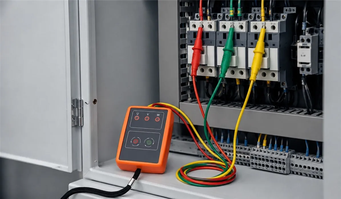
A three-phase motor can be wired, energized and apparently healthy—yet still rotate in the wrong direction. For pumps, fans, compressors, conveyors and machine tools, that mistake can mean poor performance, a failed process or mechanical damage.
A phase rotation tester gives technicians a fast way to confirm the order in which the three supply phases reach their peaks. It is also called a phase sequence tester or phase rotation indicator. Used correctly, it helps verify a three-phase installation before equipment is placed into service.
Quick answer: connect the tester's three leads to the three energized phase conductors in the order specified by its manual. Confirm that all phases are present, then read the clockwise/positive or counter-clockwise/reverse indication. The result describes the sequence at that test point. It does not, by itself, guarantee the actual rotation of every connected motor.
What does a phase rotation tester measure?
In a balanced three-phase AC system, the three phase voltages are separated in time by 120 electrical degrees. A phase rotation tester determines the order of those phases, commonly expressed as L1-L2-L3, R-S-T, A-B-C or U-V-W.
The instrument compares the timing of the three inputs and indicates one of two sequences. Manufacturers may label them clockwise and counter-clockwise, positive and negative, normal and reverse, or ABC and ACB. These labels describe the order seen at the tester's connected leads.
If any two supply phases are interchanged, the phase sequence reverses. On a directly connected three-phase motor, interchanging two phases will normally reverse the rotating magnetic field and the motor direction. Work on the circuit must follow the approved isolation, verification and commissioning procedure for the installation.
Phase sequence, phase rotation and motor rotation are not identical
These terms are often used as if they mean the same thing, but the distinction matters during commissioning.
| Term | What it describes | How it is checked |
|---|---|---|
| Phase sequence | The time order of the three supply phases at a test point | Three leads connected to an energized three-phase source |
| Phase rotation | A common field term for the supply sequence or rotary field direction | Phase rotation indicator or compatible multifunction tester |
| Motor rotation | The physical direction in which a particular motor shaft turns | Motor rotation function, manufacturer procedure or controlled commissioning check |
A phase sequence reading is only one part of proving correct machine operation. Terminal markings, motor winding connections, gearboxes, belts and mechanical layout all affect the final direction of motion. The required direction must come from the machine or motor documentation—not from assuming that a clockwise tester symbol always means the machine will run correctly.
When should phase sequence be checked?
Phase sequence should be considered whenever three-phase conductors may have been installed, moved or reconnected. Typical situations include:
- Commissioning a new motor, pump, compressor, fan or conveyor
- Replacing a motor, contactor, disconnect, transformer or distribution board
- Connecting a temporary generator or alternative supply
- Restoring equipment after cable or switchgear maintenance
- Checking multiple outlets or panels that should have consistent phase sequence
- Investigating a machine that runs backward after electrical work
Checking at only one point may not be enough. A supply can have the expected sequence at the incoming panel but be reversed farther downstream if two conductors have been interchanged. For critical equipment, verify the sequence at the relevant connection point.
How to use a phase rotation tester
The exact controls, lead colors, indication pattern and operating limits vary by model. Always use the procedure supplied with the instrument. The following workflow explains the general logic.
1. Confirm that the instrument suits the circuit
Check the tester's permitted line-to-line voltage, frequency range, measurement category and environmental limits. Confirm that the leads, probes and clips have compatible ratings and are undamaged. A voltage range printed on the front is not a substitute for reviewing the complete instrument and lead system.
2. Identify the three test inputs
Match the tester inputs and leads according to its markings. Depending on the market and manufacturer, the inputs may be labelled L1-L2-L3, R-S-T, A-B-C or U-V-W. Do not assume that lead colors have a universal meaning.
3. Make connections using the approved procedure
Only a qualified person should work on energized three-phase equipment. Follow the site's risk assessment, personal protective equipment requirements and safe connection procedure. Where the procedure calls for connection while de-energized, isolate the circuit, verify the absence of voltage with an appropriate device, attach the clips securely and then energize under controlled conditions.
Keep fingers behind probe guards and maintain the required clearances. Loose clips can produce an unreliable result and create an additional hazard.
4. Confirm phase presence before reading sequence
Many testers have three separate phase-presence indicators. Confirm that the instrument recognizes all three phases. A missing indicator may result from an open phase, insufficient input voltage, a poor connection or a lead connected to the wrong point.
A sequence indication should not be trusted until the connections and phase-presence indications are valid.
5. Read and document the sequence
Observe the tester's directional LEDs, display or audible signal. Record both the connection order and the indicated sequence. Writing only “clockwise” is incomplete if another technician does not know which tester lead was connected to each conductor.
A useful record is: “Tester L1-L2-L3 connected to panel terminals A-B-C; positive sequence indicated.” This creates a result that can be repeated at the motor disconnect or another panel.
6. De-energize and correct the wiring if required
If the sequence does not match the commissioning requirement, isolate the circuit and verify that it is de-energized before making any wiring change. Reversing two phases will reverse the sequence, but the conductors to be interchanged should be selected according to the installation drawings and approved work method.
7. Retest after the change
Repeat the same test at the same point and document the new result. Then verify actual equipment operation using the machine manufacturer's commissioning procedure. A wiring change is not complete until the original condition has been retested.
How to interpret common indications
| Tester indication | Likely meaning | Next check |
|---|---|---|
| All phases present; positive/clockwise | The connected phases follow the tester's positive sequence | Compare with the required sequence and verify the machine direction |
| All phases present; negative/reverse | Two phases are reversed relative to the tester connection order | Check drawings and correct only after isolation |
| One phase indicator missing | Open phase, weak connection, wrong test point or voltage outside the tester's range | Verify the connection and measure line voltage with an appropriate instrument |
| Unstable or alternating result | Intermittent contact, unstable supply, severe distortion or improper connection | Stop and verify leads, voltage, frequency and circuit condition |
| No indication | Insufficient input, failed connection, incorrect setup or instrument problem | Follow the manual's functional check before continuing |
What changes when a VFD is involved?
A variable-frequency drive separates the incoming supply from the motor output. The drive rectifies the input and electronically creates a new variable-frequency output. For many drives, changing the phase order on the input side does not change motor direction.
Motor direction may instead be controlled by the output lead order, drive parameters or control commands. Do not connect a phase rotation tester to a VFD output unless both the tester and drive manufacturer explicitly permit that method. The non-sinusoidal PWM output can fall outside the assumptions and ratings of a conventional phase sequence tester.
When troubleshooting a VFD-driven motor, treat the incoming supply sequence, drive output and commanded motor direction as separate questions.
Common mistakes that produce the wrong conclusion
- Confusing a positive phase sequence with correct machine direction. The tester cannot know the required mechanical direction.
- Ignoring a missing-phase indication. A directional light is meaningful only when all required inputs are valid.
- Assuming lead colors are universal. Follow the labels on the specific instrument.
- Testing only at the main supply. Two conductors may be interchanged downstream.
- Using clips with exposed or damaged insulation. Accessories are part of the measurement system.
- Using an instrument outside its voltage or frequency range. The result may be unreliable and the connection unsafe.
- Testing a VFD output as if it were a normal sine-wave supply. Follow the drive manufacturer's procedure.
- Changing wiring without documenting the original state. Record the test point, lead order and indication.
What B2B buyers should compare
For distributors and private-label buyers, the useful specification is not simply “three-phase tester.” Compare the product against the work your customers actually perform.
- Function: phase sequence only, open-phase indication, or combined phase and motor rotation
- Input range: supported line-to-line voltage and frequency
- Safety: measurement category, rated voltage, insulation and available compliance documentation
- Indication: separate phase-presence LEDs, direction display and audible feedback
- Power: self-powered from the circuit or battery-powered
- Duty limits: maximum connection time at the rated voltage
- Accessories: lead length, fused leads where required, insulated probe tips, alligator clips and carrying case
- Field durability: housing protection, drop resistance, operating temperature and storage design
- Localization: lead markings, manual languages, packaging and warning labels for the target market
The ZYD SM852B phase rotation tester is designed for phase-sequence and open-phase checks on three-phase AC systems. Its product page lists a 60 V to 600 V operating range, 20 Hz to 400 Hz frequency range, LED indication and an audible buzzer. Buyers should confirm the exact model configuration and required documentation for their destination market before ordering.
For a broader commissioning workflow, see our instrument startup checklist. You can also browse the ZYD test and measurement catalog for complementary electrical test instruments.
Phase rotation tester checklist
Before testing, confirm:
- The technician is qualified for the circuit and task
- The tester and leads are undamaged and correctly rated
- The circuit voltage and frequency are within the stated limits
- The three tester inputs are identified correctly
- The connection and disconnection procedure is understood
- All three phases are present before interpreting rotation
- The required machine direction is known from approved documentation
- The test point, lead order and result will be recorded
- The result will be verified after any wiring change
Frequently asked questions
What is the difference between a phase rotation tester and a multimeter?
A multimeter measures electrical values such as voltage, resistance and current. A phase rotation tester compares the timing order of three AC phases. A multimeter can confirm that line-to-line voltages are present, but a conventional DMM does not normally identify the three-phase sequence.
Can a phase rotation tester detect a missing phase?
Many models include separate phase-presence or open-phase indicators, but this function is model-dependent. Check the manual and confirm that all required phase indicators are valid before reading the sequence.
Does clockwise phase rotation mean the motor will rotate clockwise?
Not necessarily. The tester reports the sequence relative to its lead connections. Actual shaft direction also depends on motor terminal connections and the mechanical arrangement. Verify the required direction using the machine manufacturer's procedure.
How do you reverse three-phase rotation?
Interchanging any two phases reverses the phase sequence and will normally reverse a directly connected three-phase motor. The circuit must be isolated and verified de-energized before wiring is changed, and the result must be retested afterward.
Can a phase rotation tester be used on a VFD output?
Do not assume so. A VFD output is a PWM waveform rather than a normal utility sine wave. Use only a method explicitly approved by both the tester and drive manufacturer.
Why does a phase rotation reading change between panels?
Two conductors may have been interchanged between the test points, or the lead order may not have been kept consistent. Record the connection order at each location and verify the circuit drawings.
Build the test kit around the commissioning task
A phase rotation tester should make the technician's decision clearer: are all three phases present, what sequence reaches this point, and is the result consistent across the installation? The right model combines readable indication, suitable voltage and frequency coverage, appropriately rated accessories and documentation that matches the target market.
If you source phase rotation testers or other electrical commissioning instruments for distribution, wholesale or private-label programs, ZYD can help compare models by application, market requirements, accessory package and OEM needs. Send us the circuits and equipment your customers work on so we can recommend a practical product combination.