Sep 11, 2026Buying Guides
Insulation Resistance Tester vs Multimeter: Why a DMM Cannot Replace a Megohmmeter
Compare an insulation resistance tester vs multimeter, learn why test voltage matters, and choose the right tool for motors, cables, HVAC and maintenance.
A digital multimeter and an insulation resistance tester can both display resistance, but they are designed to answer different questions. A multimeter checks ordinary resistance and continuity with a low-level test signal. An insulation resistance tester—also called a megohmmeter—applies a specified DC test voltage and measures very small leakage currents through insulation.
That difference matters when testing motor windings, cables, transformers, switchgear, heating elements, or HVAC compressors. A circuit can look open on a multimeter and still have insulation that breaks down when exposed to a higher electrical stress.
This guide explains the practical differences between an insulation resistance tester and a multimeter, when each tool belongs in a technician’s kit, and what distributors and professional buyers should compare before sourcing a model.
INSULATION RESISTANCE TESTER VS MULTIMETER: THE SHORT ANSWER
Use a digital multimeter for general electrical troubleshooting: voltage, current, continuity, resistance, diode checks, and related measurements supported by the instrument.
Use an insulation resistance tester when the objective is to evaluate the condition of insulation at a defined test voltage. It is intended for de-energized equipment and is commonly used on cables, motors, generators, transformers, switchgear, and other insulated electrical assets.
A multimeter may find a direct short, an open winding, or an obviously low-resistance path. It cannot reproduce a proper insulation resistance test simply because its display includes a high resistance range.
KEY DIFFERENCES AT A GLANCE
Comparison Point | Digital Multimeter | Insulation Resistance Tester
Primary purpose | General electrical measurement and troubleshooting | Assessing insulation condition and leakage
Resistance test signal | Low-level internal test signal | Controlled DC test voltage, commonly selectable by application
Typical resistance range | Ohms through megohms, depending on model | Megohms and gigohms, depending on model
Best at detecting | Open circuits, shorts, component resistance, continuity faults | Moisture, contamination, deteriorated insulation, and voltage-dependent leakage
Testing energized equipment | Some functions are designed for live-circuit measurements when the meter, leads, and procedure are suitable | Insulation testing is performed only on isolated, verified de-energized equipment
Timed diagnostic tests | Usually not provided in resistance mode | May include timed readings, DAR, or PI
Post-test discharge | Not relevant to ordinary ohms mode | Important because the test object can retain charge
WHY A MULTIMETER CANNOT PROPERLY TEST INSULATION
- The test voltage is too low
A multimeter measures resistance by applying a small internal stimulus and observing the resulting current. That is appropriate for checking resistors, wiring continuity, switches, and many common circuit faults.
An insulation tester uses a much higher, controlled DC test voltage. Common handheld settings include 50 V, 100 V, 250 V, 500 V, and 1,000 V, although available outputs vary by model. The correct setting must come from the equipment manufacturer, the applicable standard, or an approved maintenance procedure—not simply from the highest voltage the tester can produce.
Some insulation defects are voltage-dependent. Cracked, damp, dirty, or carbon-tracked insulation may appear acceptable under a multimeter’s low test signal but leak significantly at the specified insulation test voltage.
- The measurement range and sensitivity serve a different job
A standard multimeter may display values in megohms, but that does not make it an insulation tester. Insulation assessment often requires measuring extremely small leakage currents and reporting resistance into the megohm or gigohm range while maintaining a controlled test voltage.
The two instruments therefore use the same electrical relationship—voltage divided by current—but operate under different test conditions. The meaning of the result is not interchangeable.
- Insulation behavior changes during the test
When DC voltage is applied to insulation, the measured current can include capacitive charging current, absorption current, and leakage current. The reading may rise as the time-dependent components decrease.
That is why professional maintenance programs may use a defined spot-test duration or timed ratios such as dielectric absorption ratio (DAR) and polarization index (PI). Exact timing, interpretation, and acceptance criteria depend on the asset, instrument, procedure, and applicable standard. A single multimeter resistance reading does not provide the same information.
WHAT EACH TOOL CAN TELL YOU
Use a multimeter to answer:
• Is supply voltage present?
• Is a fuse open?
• Does a conductor have continuity?
• Is a switch or contact making a conductive path?
• Is a winding open or obviously shorted?
• What are the voltage, current, frequency, capacitance, or temperature values supported by the meter?
For general service work, a professional model such as the ZYD ZL116 True RMS rechargeable digital multimeter — https://www.zydhardware.com/products/zl116-600v-true-rms-rechargeable-digital-multimeter is intended for everyday electrical and HVAC troubleshooting.
Use an insulation resistance tester to answer:
• Is the insulation restricting leakage at the specified test voltage?
• Has a cable’s insulation deteriorated after installation or service?
• Is moisture or contamination affecting a motor or compressor winding?
• Is insulation condition trending downward across repeated maintenance tests?
• Does a de-energized asset meet the acceptance criteria defined by its manufacturer or test procedure?
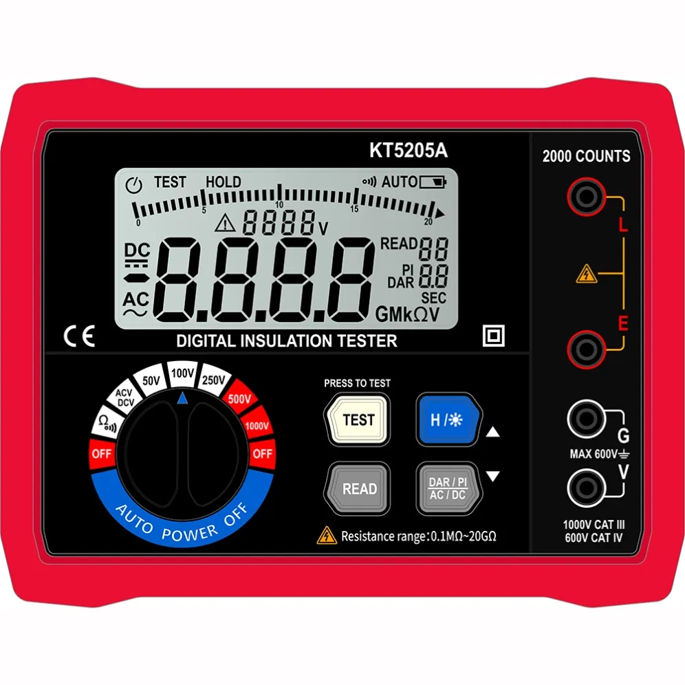
ZYD’s KT5205A insulation resistance tester — https://www.zydhardware.com/products/2026-new-kt5205a-automatic-range-megohm-meter-1000v-20gohm-digital-insulation-resistance-tester supports insulation testing up to 1,000 V and a stated resistance range from 0.1 MΩ to 20 GΩ. Buyers should match these capabilities to the intended equipment and required test procedure.
COMMON APPLICATIONS
Motors and generators
Insulation resistance testing can be performed between windings and ground or between isolated winding groups, as specified by the equipment procedure. For trend analysis, record test voltage, test duration, temperature, humidity, and equipment condition. Comparing readings taken under inconsistent conditions can lead to poor conclusions.
Power and control cables
A continuity test confirms that a conductor path exists. It does not confirm the condition of insulation between conductors or from conductor to ground. An insulation tester addresses that second question after the cable has been isolated from connected equipment.
HVAC compressors and refrigeration equipment
A multimeter is useful for supply-voltage checks, winding continuity, capacitors, and general troubleshooting. An insulation tester is used to evaluate winding-to-ground insulation. Variable-speed drives, control boards, sensors, and other electronics must be isolated as required before applying an insulation test voltage.
Switchgear, transformers, and industrial equipment
Insulation readings support commissioning and preventive maintenance, but pass/fail limits should not be invented from a generic chart. Use the manufacturer’s documentation, asset history, applicable standard, and site procedure.
SAFETY: THE MOST IMPORTANT DIFFERENCE
An insulation tester intentionally generates a significant DC voltage. It must never be connected to an energized circuit in insulation-test mode.
Before testing, a qualified person should follow the applicable lockout/tagout and verification procedure, confirm that the equipment is de-energized with suitable test equipment, and isolate components that could be damaged by the test voltage. Electronic power supplies, PLCs, variable-speed drives, UPS systems, battery chargers, surge-protection devices, and control electronics may require disconnection according to their manufacturers’ instructions.
Long cables, large motors, and other capacitive loads can retain charge after the test. Allow the tester’s discharge process to complete, follow the equipment procedure, and verify that voltage has decayed to a safe level before touching conductors.
Instrument category ratings, lead ratings, probe condition, PPE, and safe work practices still matter. For a separate explanation of measurement environments, see ZYD’s guide to CAT III vs CAT IV multimeter ratings — https://www.zydhardware.com/posts/cat-iii-vs-cat-iv-multimeter-understanding-measurement-categories.
HOW TO CHOOSE AN INSULATION RESISTANCE TESTER
For distributors, wholesalers, and private-label buyers, the best specification is not automatically the highest number. Start with the assets and end users the product must serve.
Buyer checklist
• Required test voltages: Match the selectable outputs to the equipment manufacturers’ procedures and relevant standards.
• Resistance range: Confirm the model covers the expected values with a clear specification for accuracy and resolution.
• Timed-test functions: Decide whether users need basic spot tests, a timer, DAR, PI, or data logging.
• Live-voltage warning: A warning function can help alert the user to an energized test object, but it does not replace proper verification.
• Discharge behavior: Review how the tester discharges capacitive loads and indicates residual voltage.
• General measurement functions: Some users prefer a dedicated tester; others need AC/DC voltage and continuity in the same instrument.
• Safety documentation: Check the declared rating, applicable standards, test reports, manual warnings, lead specifications, and labeling consistency.
• Field usability: Consider display legibility, test-lock operation, battery system, portability, protective case, and lead storage.
• Supply program: For distribution, compare sample availability, mixed-SKU support, packaging, user-manual localization, barcode labels, and OEM branding.
COMMON MISTAKES TO AVOID
• Using a multimeter’s high-ohms range as a substitute for an insulation test. The test conditions are different.
• Selecting the maximum test voltage by default. Use the voltage specified for the asset and procedure.
• Testing an energized circuit. Insulation testing is performed on isolated, verified de-energized equipment.
• Leaving electronics connected. The test voltage can damage sensitive components.
• Ignoring stored charge. Complete the discharge procedure and verify the result.
• Judging condition from one unexplained number. Record voltage, time, temperature, humidity, and asset condition; use consistent trend data where required.
• Applying a universal pass/fail value. Acceptance criteria depend on the equipment, manufacturer, standard, and maintenance objective.
FREQUENTLY ASKED QUESTIONS
Can a multimeter measure insulation resistance?
A multimeter can measure ordinary resistance and may detect a direct short or open circuit. It cannot perform a specified insulation resistance test unless the instrument is specifically designed with an insulation-test function and controlled high-voltage output.
Is an insulation tester the same as a megohmmeter?
In common industry usage, yes. “Megohmmeter” describes an instrument intended to measure very high resistance, while “insulation resistance tester” describes its main application. “Megger” is also widely used informally, although it originated as a brand name.
What test voltage should I use?
Use the voltage specified by the equipment manufacturer, applicable standard, or approved test procedure. Do not choose a voltage solely because it is available on the tester.
Can I insulation-test a motor connected to a VFD?
Do not apply insulation test voltage through a connected variable-frequency drive or other sensitive electronics. Isolate the motor and drive as required by their manufacturers and the site procedure.
Why does the insulation resistance reading rise during a test?
Capacitive charging and dielectric absorption currents decrease over time, so the calculated resistance may rise. The pattern depends on the insulation system, test duration, condition, temperature, and moisture.
Do I need both instruments?
Many electrical and HVAC technicians do. A multimeter handles general troubleshooting and verifies voltage; an insulation tester evaluates insulation at a defined test voltage. Combination instruments can provide both functions, but each function must still meet the application’s range, safety, and documentation requirements.
FINAL SELECTION ADVICE
The simplest distinction is this: a multimeter checks whether a conductive path exists and measures everyday electrical quantities; an insulation resistance tester checks whether insulation restricts leakage under a specified DC test voltage.
For buyers, that means product selection should begin with the application—not with a display count or maximum resistance figure. Define the equipment, required test voltages, resistance range, safety workflow, timed-test needs, and documentation expectations before comparing models.
If you are building a professional electrical or HVAC test-instrument range for distribution, wholesale, OEM, or private-label programs, contact ZYD — https://www.zydhardware.com/contact-us with your target applications and market requirements. We can help compare suitable insulation testers, multimeters, packaging options, and mixed-SKU supply plans.